There are many factors that come into play when installing a battery bank. When changing battery chemistry and system dynamics, a new way of thinking and operating is required as well. LiFePO4 batteries happily work within their capacity without needing to be regularly brought back to full charge, they provide constant voltage throughout their useable capacity, and they can take all charge supplied to them until full.
LiFePO4 Battery Basics
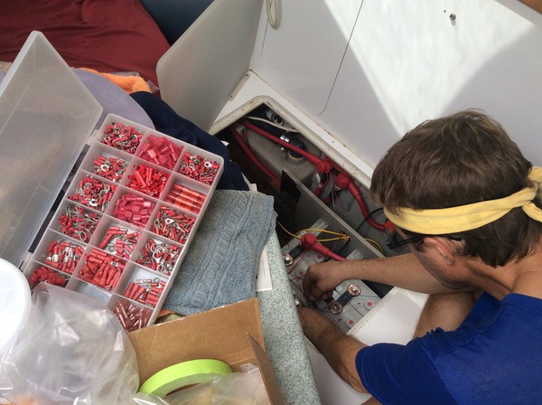
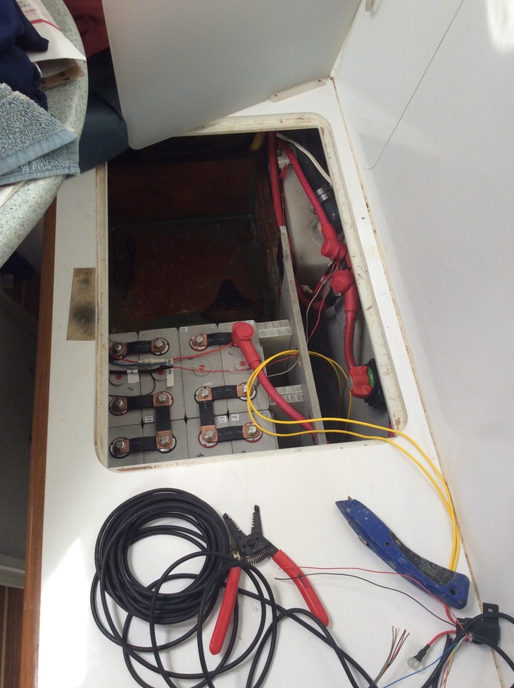
Our LiFePO4 batteries (China Aviation Lithium Battery Co. ~ CALB) were installed in a 2P4S configuration after a top balance. Out of eight cells (nominal 3.2V, 180 Ahr), we created pairs of two cells in parallel, in each case to double the capacity to 360 Ahr. Four of these pairs are then placed in series to multiply the voltage of the bank to 12.8 V nominal.

Short copper connectors are used to create the 2P4S configuration and the positive and negative battery terminals are placed on either end of the series. A Junsi cell log is wired into the bank, which monitors voltage for individual pairs of cells (2P) and the entire bank (2P4S).
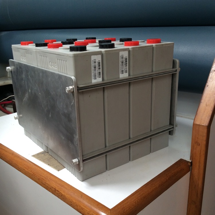
Each cell weighs 12.5lbs so the entire bank is 100 lbs and about a third as small as our 400lb lead acid bank.
Another bonus, more storage space!


We built a simple aluminum bracket to hold the bank in place as a safety feature for motion and to contain any bulge or sag.
This consists of two aluminum plates held together with threaded rod to act as book-ends, which was braced into the open space with bits of extra nidacore sheets.

Once installed, there are many peripheral factors that must be attended to: charge and discharge monitoring, inverter/charger settings, charging source regulation, and starter battery charging.
Charge and discharge monitoring

Discharge monitoring of the LiFePO4 battery bank is virtually unchanged from lead acid. Our battery monitor (Tri-metric 2020, Bogart Engineering) monitors real-time current draw and daily, cumulative discharge.
Li+ ion batteries can take and give current at high rates (i.e., have low internal resistance). Our working loads seen from normal “house" usage will be in the 1-15 A range from appliances like lights, refrigerator and computers, and on a given day we draw around 100-150 Ahrs total, depending on usage ~ well within the usable capacity of our 360 Ahr bank.
Charge monitoring takes place at several, redundant areas in Reach’s charging system and is regulated by voltage settings. Li+ ion battery charge and discharge curves are flat, yet extremely sensitive to the 10’s of millivolts (o.o1V) once you reach the “knees” of the curves at the extremes. Therefore, the most accurate monitoring we do for determining full charge of the bank is using a voltmeter to check the state of cell pairs and the whole bank. We also used the voltmeter to calibrate the battery charge monitor.
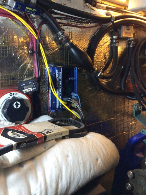
Bank charge monitor
The Junsi CellLog 8M hooks directly into the LiFePO4 bank and monitors voltage for cell pairs and the bank itself. For such a small package it is extremely versatile and alarms can be set for various parameters. We set this alarm to go off for the following scenarios:
*Voltage alarms for the bank (14.0V/12.4V = high/low): monitors bank within middle 80% of working range.
*Voltage alarms for each cell pair (3.5V/3.1V = high/low): monitors cell pairs within middle 80% of working range.
*Voltage difference between pairs (delta > 0.150 V): monitors cell pair balance.

Inverter/Charger
Our Victron Multiplus 12V/3000W/120A/120AC inverter/charger is programmable and supplies 120V AC power to the boat, as well as charges the batteries when external AC power is available from shore or generator.

The Victron charger is now set at a 13.8V cut-off for the LiFePO4 battery bank. This is a hard cut-off, not an alarm. If this voltage is reached, the charger stops and no further charge will reach the batteries. This charging regimen is significantly different than how the Victron operated for lead acid batteries, where the bank was charged to 14.8V, followed by a long absorption phase at reduced current and a float phase at a trickle current.

A low voltage cut-off was also programmed into the Victron inverter for 12.4V. In practice, we can’t imagine how our power draw would ever draw the battery bank so low. However, since the inverter can draw up to 250A, and the bank can deliver much more than that, we may have the option of running our AC water maker (CruiseRO Water) directly off of the bank in the future. We will test and report back on this option in a future LiFePO4 performance evaluation.
Charging sources
Each of our charging sources were chosen to have customizeable regulation. In practice, if one charging source meets the charge limit, the shut-off should be coincident at all charging sources.
Alternators
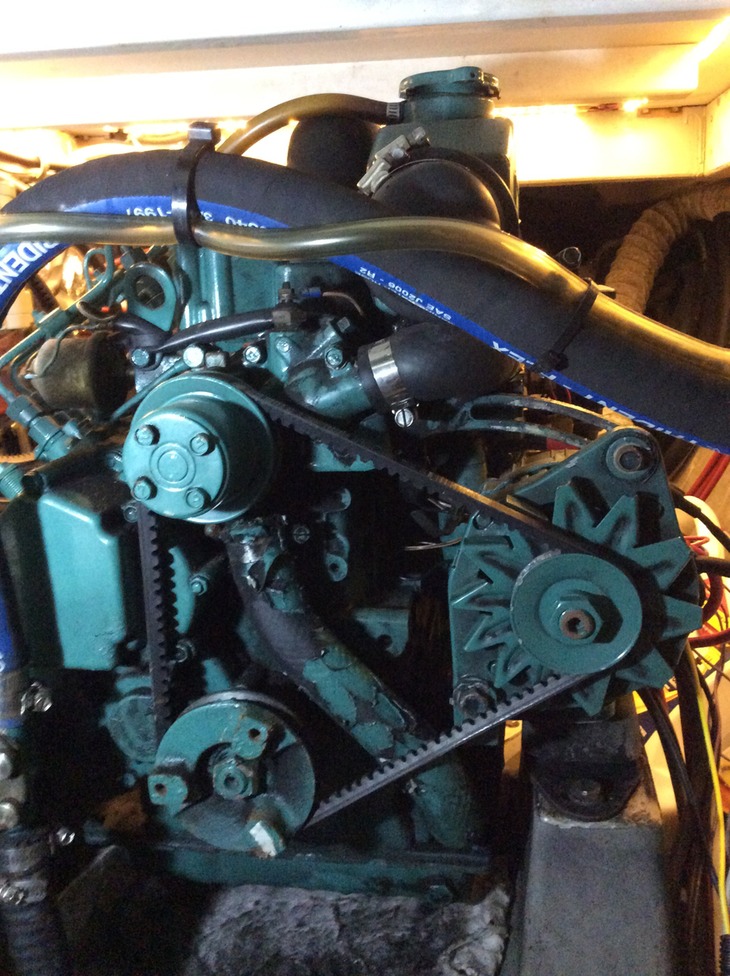
We have two different-sized alternators from two different vendors, one for each of our two Volvo MD2030 engines. Each are regulated and now set to a voltage cut-off of 13.8 V, using a sense wire that is led back directly to the battery bank. The alternators charge the bank via direct connection with 1/0 cable to the batteries and the regulators are set to shut-off all current flow once the voltage limit is reached.

Knowing that the LiFePO4 bank will become extremely sensitive to millivolt (0.01V) differences as it approaches its charging knee, this sense wire needs to be monitoring the bank directly to ensure that there is no unintended voltage drops from tapping into other places in the circuit.
For example, the lead acid battery sense wires were connected directly to the battery combiners to read house voltage, yet they worked fine within a 0.1V tolerance for activation and transition to absorption and float stages.
Each of our alternators were de-rated as follows for safety and lifetime considerations. Since the LiFePO4 battery bank will accept as much charge as you can give it, this can cause the alternators to continually run hot and could eventually burn out the windings. Therefore, temperature sensors were also placed on the alternators and will decrease the current 50% if the following maximum temperatures are reached.
120A Balmar alternator -> de-rated to 100A; 13.8V voltage cut-off; 210˚F max temperature.
60A Valeo alternator -> de-rated to 40A; 13.8V voltage cut-off; 190˚F max temperature.
Solar
Our solar array has an output of 700W. We can see up to 35A of real-time current and over 200Ahr a day coming into the battery bank under sunny conditions. Since the LiFePO4 battery bank can take all of the current you can give it, this charging source is a good match to the new system. This is also delivered directly to the bank.

The MPPT solar controller (MorningStar TriStar60) is set for a 13.8V cut-off using a sense wire connected directly to the bank, after which it shuts off so that no further current will flow to the battery bank.
The way this programming works is that if the cut-off is reached, it will remain off until it resets itself over the night-cycle.
It will turn charging back on at the start of the next day when the sun rises and activates the panels.
It would be nicer if the controller could be programmed to re-engage at a given state of charge (SOC) of the battery bank, say when it dips below 30% SOC.
Starter battery charging
Each Volvo engine on Reach has its own, local 12V lead acid starter battery in the engine compartment. These were charged using a battery combiner to our lead acid battery bank. The combiner closed a solenoid when the bank hit 13.1V during charging and opened the solenoid when the voltage went below 12.7V. Since LiFePO4 battery banks are operating continually above 13.1V state of charge range, this solenoid would always be closed and the starter battery charging.
How to charge these starter batteries posed a bit of a conundrum. As we saw it, there are at least three options:
1. Status quo: Keep things wired and charging as they are via combiner. So the solenoid will be closed all the time… lead acid batteries are always wanting to be charged to the fullest and will keep taking charge, right?! We haven’t figured the potential downside of this option yet.
2. DC/DC Converters: One could buy two DC/DC converters (~$300 ea) to charge the start batteries at lead acid battery charge regimens from the LiFePO4 house bank. This would charge the starting batteries at 14.2V from the 13.2V house bank.
3. Relay to new solenoid: Install a relay (i.e., normally open solenoid ~ 1” Bosch automotive relay 70A, 30V) connected to the 12V tap on the alternator, the low voltage output used for dash lights, etc. Connect the ground wire of the combiner to the relay. When the alternator is running, 12V shows up on the 12V tap, the new relay shuts and the combiner is re-connected to ground and the house bank will be on-line with the starter battery. Since the LiFePO4 bank will usually be operating above the 13.1V, the combiner will close as it is designed to do and charge the starter battery (repeat other side!).

Mark implemented option #3 on Reach, to charge the start batteries using a new relay, so that the batteries will only be charging when the engine(s) are running.
The implication of leaving them on-line all of the time (option #1) were a bit unknown, so the relay (option #3) adds at least some level of charging control.
The only trade-off to this option and Status quo (option #1) is that the lead acid batteries will never see a charging voltage of 14.2-14.4V that they would like to see to get into full absorption. The effect of this may be to slowly sulfate out the batteries and/or result in a decreased lifetime. Since these 12 V automative batteries are readily available and only cost around $100 or less, these options are still more economical than spending $600 in DC/DC converters to get exactly precise charging for these basic starter batteries.

Overall, the installation of the LiFePO4 battery bank was relatively easy once all of these practical considerations were addressed. As mentioned in the design phase, we are not using a battery management system (BMS). At the outset, we found differences in cell coulombic efficiencies (charge/discharge dynamics) and this affected the pairing process of the cells when building the bank. As we utilize this system more, we will report back on our findings on this issue and overall performance of the bank.