
The last big project of the year is to convert our battery bank from flooded lead acid batteries to a lithium iron phosphate (LiFePO4) bank. Mark has been researching and planning for this conversion for ages now… just waiting for our current batteries to die. The current lead acid batteries were replaced after our lightning strike in 2011, so they are 5 years old and approaching their useful lifetime. We also wanted to do this while Reach is located in the States where we had access to convenient shipping and peripheral supplies.
Trying to grasp the main drivers for our dollar investment, I considered the placement of the system in the overall scheme of things and have also attempted to crudely visualize what the battery difference will mean in practice. We’re not going to dive deep into technical discussion here, but suffice it to say that Mark would be happy to answer questions regarding any details.
There are plenty of considerations when designing something as important as your boat’s power plant, the main components of which every boater knows well, consisting of charging sources that feed into the eventual output of power supplied to our floating home.


Regarding the battery bank, the factors that went into our decision on which type to purchase related to how the main battery types compare in cost, weight, capacity and lifetime.
When researching LiFePO4 batteries, we found the prices for cells much lower in the electric car realm ($225/cell) than in the marine industry.
Therefore, lithium ion cells have recently come down to a reasonable price range for a bank (even though you can’t beat cost of lead acid), considering that you only need one-half of the total charge capacity for an equivalent usable range. The weight and size difference is significant. Reach is a loaded, live-aboard catamaran, so we’ll gladly take a few hundred pounds off! The working cycle range is also higher and it will be interesting to see how this translates to years of use.
So, we made the plunge and purchased eight LiFePO4 cells. They are currently configured in parallel for an initial charging regimen where Mark intends to carefully take them to a state of full charge for a top-balance so that all of the cells start at the same charge state. After installation, the charging and discharging can take place anywhere in the middle state of charge, on the "flat part of the curve". This is where the real benefit of the Li-ion batteries comes into play, they can be charged and discharged continually anywhere within an 10% - 90% state of charge and do not need (nor want) to be “topped off”.
Charge curves
I am a visual learner and made simple cartoons to see what the charging differences are when going from lead acid to LiFePO4 banks. Mark has shared his thoughts with several cruising friends who are also interested this conversion so I’ve included his notes on this topic.
To me, these curves show the advantage of charging LiFePO4 batteries over lead acid, where the last 20% of charging for lead acid always seems to take forever (if overcharged, they’d just boil a bit), but they liked and needed to get back to 100% charge to have the best usable capacity and lifetime.
Conversely, the LiFePO4 batteries can stay charged anywhere from the 10% to 90% state of charge and can take a 3C charge rate (3x bank capacity ~ important for electric cars). Even though all of our charging systems together can only deliver 400A to the bank, it can accept up to around 1000A. Reaching any higher than a 90% state of charge is a danger zone where you risk thermal runaway and lithium metal plating. This upper voltage cutoff will be controlled using a cell overcharge monitor and settings on the inverter/charger.


Mark’s notes: We really didn't need to change much of our charging infrastructure because I have been planning for this future lithium bank when replacing failed equipment or adding new over the past several years.
However, it is not complicated. The only requirement for the use of lithium batteries in a cruising boat is that they are only charged to 3.4-3.5V per cell and that charging stops fully when they hit those voltages and ideally doesn't resume again until they drop below 3.2V.
So if you have fully user-adjustable charging sources, then no changes are needed. Our solar charger, both mains chargers and one of our alternator regulators are this way. We had to add another different alternator regulator on the other alternator because it was not sufficiently adjustable for Li.
Relating to solar [charging], lithium batteries actually prefer to be in a partial state of charge and there is no reason to ensure that they regularly be charged back to full, like is critical for flooded, AGM and gel batteries. So the solar doesn't need to be sized to keep the batteries charged - it only needs to be sized to keep some charge in the batteries. It's OK to wander around forever in the 10-80% state of charge range and spend days or weeks (or years) in the lower 30%.
If you ever do want to throw some charge in them, they will take all the current you can give them and come up quickly (that is the same principle behind how your cordless tool Li batteries can be recharged from empty to full in 15min).
Discharge curves
I used the same visual approach to understand the discharge curves, including Mark’s notes. This is where the advantage LiFePO4 usage in practice makes the most sense. The usable area under the discharge curves are virtually the same for lead acid and LiFePO4 batteries, even though the latter is one-half the total capacity sized bank.
With lead acid batteries, if you discharge them under 50% you will soon degrade the cells and precipitate out sulfate that will eventually deplete the absolute cell capacity.
The flat discharge curve of the LiFePO4 bank allows care-free use of boat power over 80% of the curve, as long as you avoid extreme charging and discharging. In those end ranges, the battery bank requires very reliable control of the discharge cut-off using the cell monitor, fail-safe relays and programming on our Victron inverter/charger.
We are not going to use a battery management (BMS) system that is frequently sold with marine Li-ion solutions. After a top-balance during initial charging, we see no need for balancing the individual cells as long as we monitor voltage and operate in the safe part of the curve.


Mark’s notes: The whole need for a complicated battery management system and expensive relays, etc is unnecessary for the way batteries are used on a cruising boat. They are designed for how electric vehicles use batteries - where full charge and discharge capacities are needed. As long as all charging sources are set below the non-linear upper knee of the charge curve (~14.2V), you will get 95% charged and never be anywhere near a high voltage event that the BMS is designed to handle.
Likewise, as long as you don't run the batteries down below 11V, you won't drop below 5% charged and stay out of the non-linear lower knee of the discharge curve and never be anywhere near a low voltage event that the BMS is designed to handle.
The other aspect of a BMS is cell balancing, but that is being shown to be quite ineffective and mostly unnecessary in all applications anyhow.
So the over-charging part of the BMS is taken care of by not setting any of your charging sources anywhere near the over-charge voltage limit. I plan to handle the over-discharge problem with a simple $15 cell monitor that has a programmable alarm and relay output. If for any extremely unlikely reason our reefer and LED lights draw 2 weeks of charge out of the bank without any charge going in, or without us noticing, an alarm will sound. If that alarm ever does go off, I will consider connecting the relay output to shut down the entire DC panel load.
Battery management solved for $15.
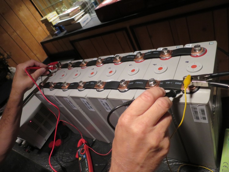
The cells are currently set up in parallel, undergoing the initial charge regimen using a Volteq 30V 20A power supply that we bought for this purpose. They are taking about a week to charge at constant voltage to reach 3.4V (each cell is a nominal 3.2V 180Ahr).


When this voltage is reached, Mark will carefully raise the voltage to get very high up on the LiFePO4 full state of charge curve to perform a top-balance of the bank. This will be the first and only time that these batteries will reach near 100% state of charge.
They will later be reconfigured to form a battery bank with 8 cells, consisting of 4 sets of 2 parallel cells (3.2V 360Ahr), hooked into series to form a nominal 12V 360Ahr bank.
Stay tuned for installation.